You have questions, we have answers!
Here is some helpful information – and if you don’t see what you’re looking for, please contact us.
Knowledge Base
DXF Information
A little information on DXFs:
DXF is a Drawing eXchange format created by Autodesk for exchanging data between various CAD packages. DXF files can be imported into most CAD software, not only Autodesk software (e.g. AutoCAD, Revit). DXF format is publicly documented, as opposed to Autodesk’s proprietary DWG format.
DXF files only store numerical coordinates but do not store measurement units for those coordinates. When importing a DXF file into CAD software; you must specify the units in order for the CAD software to set the proper scale.
Our system cannot provide DXFs in Imperial, however, upon import to AutoCAD you should be able to convert to your preferred unit of measurement.
The Measurement Tool features 3 Modes.
Standard measurements, Mode 1, are featured in every iGUIDE by default. Advanced Measurements, Modes 2 and 3, are featured as part of every Premium iGUIDE, but can also be added as a paid add-on to Standard iGUIDEs as well.
Read on for instructions on how to use Measurement Modes 1, 2, and 3.
Mode 1 – Measurements on Floor Plan
Measure the horizontal distance between any two points on the floor. This mode is useful for measuring wall to wall distances in irregularly shaped rooms or to see if your furniture will fit.
To use this feature, select Measure Mode 1, then click and drag from one point to another on the floor plan. A red line will connect the start and endpoints and its length will be reported as shown in Figure 1.

Figure 1. Measuring on a floor plan.
Mode 2 – Measurements on a Vertical Plane
Measure the distance between points located on a vertical plane using a panorama. This mode is useful for measuring features found on walls, such as windows, doors, and ceiling height.
To use this feature, select Measure Mode 2, then click and drag from one point to another on the floor plan to draw a line segment. It will get extended into an infinite line, shown in red, on the floor plan as seen in Figure 2. When projected upwards from the floor, that line will define a vertical plane. All subsequent measurements will be reported as if the points selected in a panorama were located on the plane. Most of the time that plane will be the front surface of a wall visible from the panorama. Click on any two points in the panorama to measure the distance between them. You can zoom in to the panorama for more precise positioning.
The two points must be located on the vertical plane you defined, otherwise the reported distance between them will be meaningless.

Figure 2. Measuring in a vertical plane.
Mode 3 – Dual Panorama Triangulation
Measure the distance between any two points in 3D space by using two panoramas. The two points must be clearly visible in both panoramas. This mode is useful for measuring distances that cannot be measured using Mode 1 or Mode 2.
To use this feature, select Measure Mode 3, then select the first panorama that contains the two points of interest and click on those points, remembering the order in which you do that, as shown in Figure 3. You can zoom in to the panorama for more precise positioning. The distance between the two points will initially be shown as “???”. Next, select the second panorama and click the same two points of interest in the same order. You can use zoom again for greater precision. The measurement will appear instead of the three question marks after all four points have been selected, as seen in Figure 4.
It is very important that both panoramas were shot with a camera located on the same horizontal plane (no split-level floors should be used) and using the same tripod height, otherwise, the reported distance will be meaningless.

Figure 3. Measuring in 3D space – view from the 1st panorama.

Figure 4. Measuring in 3D space – view from the 2nd panorama.
Multiple Measurements and Undo
You can make multiple measurements in Modes 1, 2, and 3 – just keep selecting new additional points. You can use the Undo button to delete the last point. In Mode 3, Undo will work only until a new pano is selected.
Measurement Uncertainty
After completing a measurement in Modes 2 and 3 you will receive a message that looks similar to this when a measurement has been taken:
“Estimated measurement uncertainty is 2. Take additional measurements by selecting new start and endpoints.”
The measurement uncertainty will vary depending on the panoramas selected and the measurement points chosen. Reduce the measurement uncertainty to the lowest possible number by trying the same measurement multiple times, using different panoramas to see what yields the best results.

Figure 5. Keep measurements in the shaded area.
When choosing a panorama in Mode 2 try to use a panorama that is close to features you are trying to measure. This makes selecting the features easier and will reduce measurement uncertainty. This can also be expressed as keeping measurements within a 90° field of view when the panorama’s viewing direction is perpendicular to the vertical plane in which measurements are taken. See the shaded area in Figure 5.

Figure 6. Keep measurements in the shaded area.
When using Mode 3, try to choose panoramas that are close to the features being measured, but that are far enough apart from each other to offer a unique and different perspective. Try to keep measurements out of the periphery of either panorama to reduce measurement uncertainty and aim to keep measurements within the shaded area in Figure 6.
Excluded Area is a sum of interior areas of all rooms (measured to the inside surface of room walls) that are excluded from the Interior Area for a floor. Prescribed area exclusions can vary from region to region. Examples of exclusions are spaces open to below, garages, cold cellars, crawl and reduced height spaces, non-enclosed open spaces, such as decks and balconies.
The footprint of all interior walls and staircases is typically included in the reported Interior Area for a floor. The PDF floor plans use color to highlight all included areas. All excluded areas are shown white.
You can share your documentation with team members, vendors or key stakeholders easily and securely. There are two ways to do this.
1. Click the “SHARE” button on the project page.

An email will open with a link you can send to anyone who needs to see your project. Just type in their email address and add any message you’d like!
OR
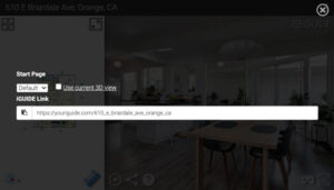
2. Click the share icon within the interactive 360 floor plan.
![]()
A dialogue box will appear with a link you can copy and paste into an email or text or any other application you use to communicate. This gives you the option to choose which page and view you would like to start with – in case you have a note or request about a specific area of the property to share with a contractor or client.
Method of Measurement
Definitions
Interior Area is a per floor calculation, made by measuring to the inside surface of the exterior walls.
Exterior Area is a per floor calculation, made by measuring to the outside surface of the exterior walls, see below for calculation details.
Grade is the ground level at the perimeter of the exterior finished surface of a house. A floor is considered to be above grade if its floor level is everywhere above grade.
Total Interior Area is the sum of all Interior Areas.
Total Excluded Area is the sum of all Excluded Areas.
Total Exterior Area is the sum of all Exterior Areas.
Unfinished Area is the sum of interior areas of all unfinished rooms (measured to the inside surface of room walls).
Finished Area is Exterior Area minus Unfinished Area. Finished Area includes the footprint of interior and exterior walls.
Exterior Area Calculation
Exterior Area = [Perimeter Wall Thickness] x [Perimeter Wall Length] + [Interior Area]
Notes
- Perimeter Wall Thickness is an independent measurement taken from the property, typically, at the main entrance. Considerations are not made for varying wall thickness around the perimeter.
- Perimeter Wall Length is the sum of lengths of all exterior wall segments on a particular floor. When used to calculate Total Exterior Area Above Grade based on Total Interior Area Above Grade, it is the sum of perimeter wall lengths of all floors above grade.
Disclaimer
All dimensions and floor areas must be considered approximate and are subject to independent verification.
Note: Floor areas include footprint area of interior walls. All displayed floor areas are rounded to two decimal places. Total area is computed before rounding and may not equal to sum of displayed floor areas.